...
...
Revision History
First Release: November 2021 (MR)
| Info |
|---|
This tutorial uses the Kinetic Control user interface released on 11/1/2021; if you are using the old user interface, please refer to the original version of this tutorial posted under “Legacy Resources” |
Section 1: Tool Length Offset Definition
The tool length offset (TLO) is the distance between the Z home position and the machine home when the tip of the tool is a specified distance from the B table. Basically, this tells the Pocket NC where the tool is in space so that the correct compensations can be made to the program in order to cut the part successfully.
The Pocket NC V2 is equipped with a tool probe that will automatically measure the tool length offset for most tools. However, some tools will still have to be measured by hand. This tutorial will explain how to use the automatic tool probe as well as how to measure the tool length offset by hand.
Section 2: Tool Change
Section 2.1: V2-10 Tool Holder Change
Turn off spindle and loosen the (3) spindle screws using the 3mm wrench.
Tap spindle holder with the back end of the 3mm wrench and take out the tool holder.
Reverse process for installing a new tool holder, being sure to tighten the (3) spindle screws incrementally.
Section 2.2: V2-10 Tool Change
Use the Pocket NC spindle wrench and the 3mm driver, both are found in the tool kit.
Turn off spindle and place the 3mm driver into one of the 3 spindle screws.
Using the Pocket NC spindle wrench loosen the collet nut while holding the spindle in place using the 3mm wrench.
Change out or move the tool and then reverse the process to tighten the tool into tool holder.
Remember to adjust or remeasure the tool offset after changing or adjusting a tool.
Section 2.3: V2-50CHB Tool Change
Rotate the spindle lock lever to the “OPEN” position (towards the front of the machine).
Remove the tool and insert the new tool with the same diameter shank.
If using a tool with a different diameter shank, the collet will also need to be swapped. Only install or remove the collet while the lever is in the “OPEN” position and while a tool is inside the collet (to prevent the collet from collapsing). Use the small wrenches provided to hold the end of the spindle still and unscrew the collet. Insert a tool in the replacement collet and repeat in the reverse order to seat the collet.
Rotate the spindle lock lever to the “LOCK” position to tighten the collet and secure the tool.
Remember to adjust or remeasure the tool offset after changing or adjusting the tool.
Section 2.4: V2-50CHK Tool Change
The 12mm and 14mm wrenches provided with this spindle option will be needed.
Use the 12mm wrench to hold the spindle in a fixed position and use the 14mm wrench to loosen the nut at the end of the spindle next to the tool.
When loose, pull out the nut, collet, and tool assembly, then pull out the tool.
If switching shank sizes, pop out the old collet and snap in the new collet. (There is a snap feature on the collet that will only snap into/out-of the nut if no tool is present).
Insert the new tool into the collet and nut assembly.
Use the wrenches to tighten the nut assembly back onto the spindle.
Remember to adjust or remeasure the tool offset after changing or adjusting the tool.
Section 3: Using the Tool Probe
Section 3.1: Tool Measurement
Do not run the probe cycle for any tool sticking out more than 1.5 inches from the end of the extended tool holder with a V2-10. On any machine, do not use the probe cycle for any tool with a diameter greater than ¼ inch. Doing so will cause a crash and may result in damage to your machine and/or a broken tool.
Ensure that the machine is connected, powered on, and has been homed. The TOOL OFFSETS table is found under the SETUP tab on the Kinetic Control user interface.
...
| Info |
|---|
If the tool that is measured is designated “T1” in the TOOL OFFSETS table, then this tool will be used anytime the G code calls upon T1. The G code matches the tool measured in the software’s user interface. |
Section 4: Measuring Tool Length Offsets by Hand
If the automatic tool length measurement probe cannot be used for a tool, you can measure the tool length offset by hand.
...
You will also need to have a 1-2-3 block. These are available through Amazon as well as many other vendors. Any precision machined or ground 1-2-3 block will work for this procedure.
Home machine and remove any fixturing and components from the B-table
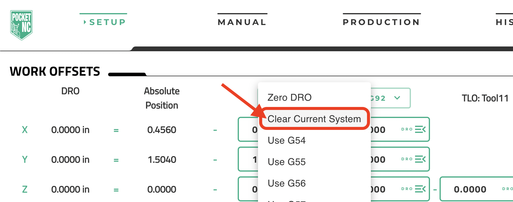
Clear any offsets in the SETUP tab, WORK OFFSETS section, by clicking the “G54” dropdown and selecting “Clear Current System”:
...
3. Move the A table to 90 degrees using the command “g90 g0 A90” within the MDI command window on the “MANUAL” tab of the UI and hit the enter key:
...