Revision History
...
| Info |
|---|
This tutorial uses the Kinetic Control user interface released on 11/1/2021; if you are using an older software versionthe old user interface, please refer to the original version of this tutorial posted under “Legacy Resources” |
...
Turn off spindle and loosen the (3) spindle screws using the 3mm wrench.
Tap spindle holder with the back end of the 3mm wrench and take out the tool holder.
Reverse process for installing a new tool holder, being sure to tighten the (3) spindle screws evenlyincrementally.
Section 2.2: V2-10 Tool Change
Use the Pocket NC spindle wrench and the 3mm driver, both are found in the tool kit.
Turn off spindle and place the 3mm driver into one of the 3 spindle screws.
Using the Pocket NC spindle wrench loosen the collet nut while holding the spindle in place using the 3mm wrench.
Change out or move the tool and then reverse the process to tighten the tool into tool holder.
Remember to adjust or remeasure the tool offset after changing or adjusting a tool.
...
Rotate the spindle lock lever to the “OPEN” position (towards the front of the machine).
Remove the tool and insert the new tool with the same diameter shank.
If using a tool with a different diameter shank, the collet will also need to be swapped. Only install or remove the collet while the lever is in the “OPEN” position and while a tool is inside the collet (to prevent smashing itthe collet from collapsing). Use the small wrenches provided to hold the end of the spindle still and unscrew the collet. Insert a tool in the replacement collet and repeat in the reverse order to seat the collet).
Rotate the spindle lock lever to the “LOCK” position to tighten the collet and secure the tool.
Remember to adjust or remeasure the tool offset after changing or adjusting the tool.
...
The 12mm and 14mm wrenches provided with this spindle option will be needed.
Use the 12mm wrench to hold the spindle in a fixed position and use the 14mm wrench to loosen the nut at the end of the spindle next to the tool.
When loose, pull out the nut, collet, and tool assembly, then pull out the tool.
If switching shank sizes, pop out the old collet and snap in the new collet. (There is a snap feature on the collet that will only snap into/out-of the nut if no tool is present).
Insert the new tool into the collet and nut assembly.
Use the wrenches to tighten the nut assembly back onto the spindle.
Remember to adjust or remeasure the tool offset after changing or adjusting the tool.
...
Section 3.1: Tool Measurement
Do not run the probe cycle for any tool sticking out more than 1.5 inches from the end of the extended tool holder with a V2-10. On any machine, do not use the probe cycle for any tool with a diameter greater than ¼ inch. Doing so will cause a crash and may result in damage to your machine and/or a broken tool.
Ensure that the machine is connected, powered on, and has been homed. The TOOL OFFSETS table is found under the SETUP tab on the Kinetic Control user interface.
...
| Info |
|---|
The “Diameter”, “Flutes”, and “Description” columns are just for you to add information for yourself. They will have no effect on the machine function and do not need to be filled, but filling in the details is the best practice for commonly used tools. The TLO field will need to be updated any time the tool’s position in the holder is changed (this can be done manually or by measuring the tool using the steps below). |
Click on the green probe icon for the tool for which that you wish to measure and set the tool length offset.
...
The machine will move the X-axis towards the front of the machine to the tool loading position and the green button on the front of the machine will begin to blink. A notification will also pop up in the lower left right hand of the UI reminding you to load a tool. If you haven’t already, install the tool you wish to measure. Make sure to fully tighten the holder as previously described.
...
After the probe cycle has finished, the tool length offset will be updated in the tool table.
...
Pictures Pictures of the tool probe cycle are shown below.
...
After the cycle is finished, the machine will return to the position it was in when the the cycle was started. Note that this could cause a collision with the part if you are swapping out a shorter tool for a longer tool. Program/adjust your G code appropriately to avoid this type of collision by retracting to a safe distance before a tool change.
...
Note, if the next tool that is measured is designated “T1” in the TOOL OFFSETS table, then this tool will be used anytime the G code calls upon T1. The G code matches the tool measured in the software software’s user interface.
Section 4: Measuring Tool Length Offsets by Hand
...
You will need to know your machine’s B Table Offset. This is the distance from B Table to Center of A axis rotation. This number is 0.8xx inches. This value changes for each machine and is included on a paper written in the back of the Quick Start Guide that is included with each machine. If you have misplaced yours, please email us at info@pocketnc.com and we can find it for you.
You will also need to have a 1-2-3 block. These are available for purchase from Pocket NC through Amazon as well as from many other vendersvendors. Any precision machined or ground 1-2-3 block will work for this procedure.
...
Home machine and remove any fixturing and components from the B-table
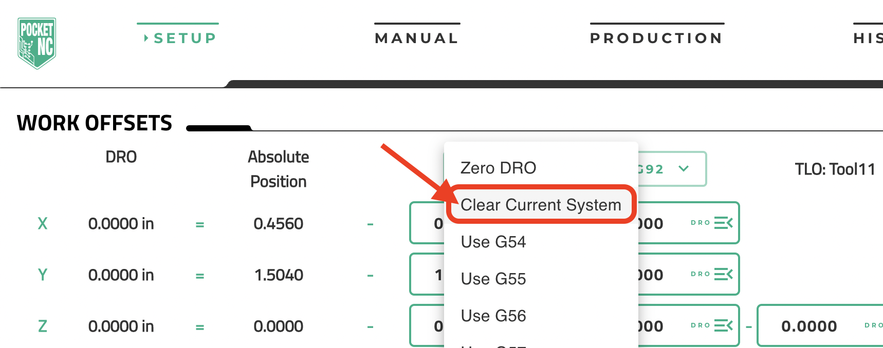
Clear any offsets in the SETUP tab, WORK OFFSETS section, by clicking the “G54” dropdown and selecting “Clear Current System”:
...
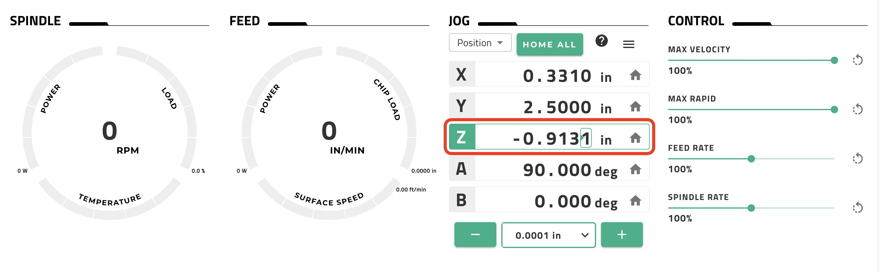
3. Move the A table to 90 degrees using the command “g90 g0 A90” within the MDI command window on the “MANUAL” tab of the UI and hit the enter key:
...
Example -(3.000)+(0.8861)+(-0.9131)=(Tool Offset) = (-3.027)
...
9. Input the calculated Tool Offset in the TOOL OFFSETS table of the SETUP tab for the appropriate tool. Click in the appropriate box in the “TLO” column (based on the tool number). Type the tool offset that you calculated and be sure to hit the ENTER key on your keyboard. Make sure that the sign is correct. Update the tool diameter if needed.
...